
Santiago Leon
Senior Product Development Engineer
Introduction to the Impact of SysML Diagrams in System Engineering
In the specialized field of system engineering, the utilization of effective tools and methodologies is paramount to the success of complex projects. Among these, SysML (Systems Modeling Language) Diagrams stand out as a pivotal element in modern engineering practices. Born from the need to address the limitations of software-centric tools in handling the multifaceted nature of systems engineering, SysML Diagrams have evolved to become a cornerstone in the discipline.
SysML Diagrams, as an extension and modification of the Unified Modeling Language (UML), are tailored specifically for systems engineering. They offer a standardized approach to visualize, specify, analyze, and document the components and dynamics of a system. The flexibility and comprehensive nature of these diagrams make them an indispensable tool for engineers, allowing them to model complex systems that include a blend of hardware, software, information, processes, personnel, and facilities.
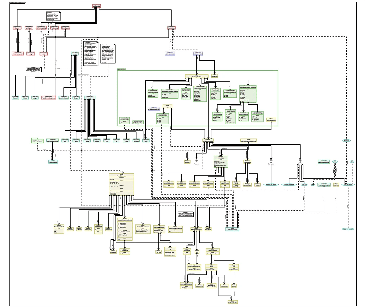
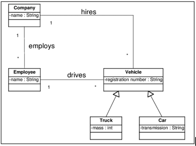
Example SysML Block Definition Diagram.
The critical role of SysML Diagrams extends beyond mere representation; they facilitate a deeper understanding of the system's interactions, behaviors, and structures. This understanding is crucial in anticipating challenges, optimizing performance, and ensuring robust system integration. As systems become increasingly complex and interdisciplinary, the role of SysML Diagrams in effective system engineering continues to grow, marking them as an essential asset in the engineer's toolkit.
In this exploration of the role of SysML Diagrams in effective system engineering, we delve into the various types of SysML Diagrams, their specific applications, and the best practices for their implementation. We will uncover the nuances that make SysML Diagrams a fundamental component in the architecture and design of complex systems.
Deep Dive into SysML Diagrams: Types and Functions
SysML Diagrams are a diverse and flexible set of tools, each serving specific purposes in the realm of systems engineering. Understanding the types and functions of these diagrams is crucial for their effective application. SysML offers nine types of diagrams, categorized into two main groups: structural representations and behavioral modeling.
Structural Diagrams
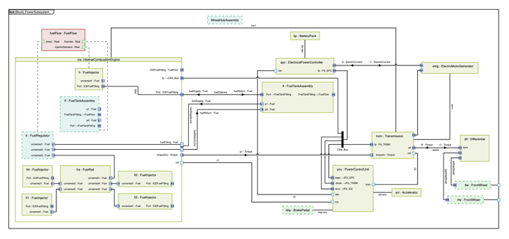
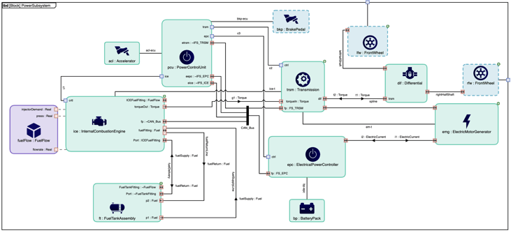
Internal Block Diagram of an electric vehicle power subsystem.
- Block Definition Diagram (BDD): This diagram is the backbone of SysML structural modeling. It defines system blocks and their relationships, illustrating system hierarchies and compositions. BDDs are instrumental in representing the physical and logical components of a system and their interconnections.
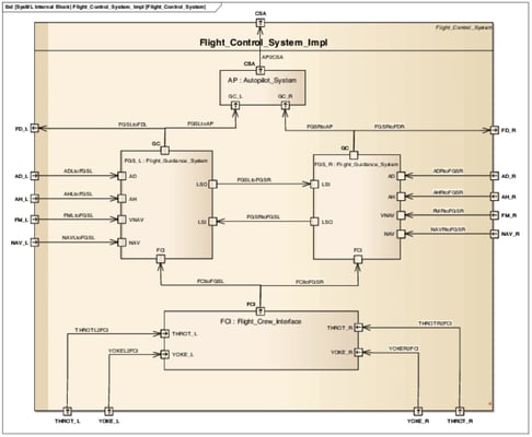
- Internal Block Diagram (IBD): IBDs take the concept of blocks further by detailing the internal structure of a system block. These diagrams show how components within a block interact, their interfaces, and the flow of information or energy between them.
- Package Diagram: Used for organizing model elements into groups, Package Diagrams are vital for managing and structuring the elements of a complex system. They depict dependencies and relationships among different packages, aiding in the modular view of the system architecture.
Behavioral Diagrams
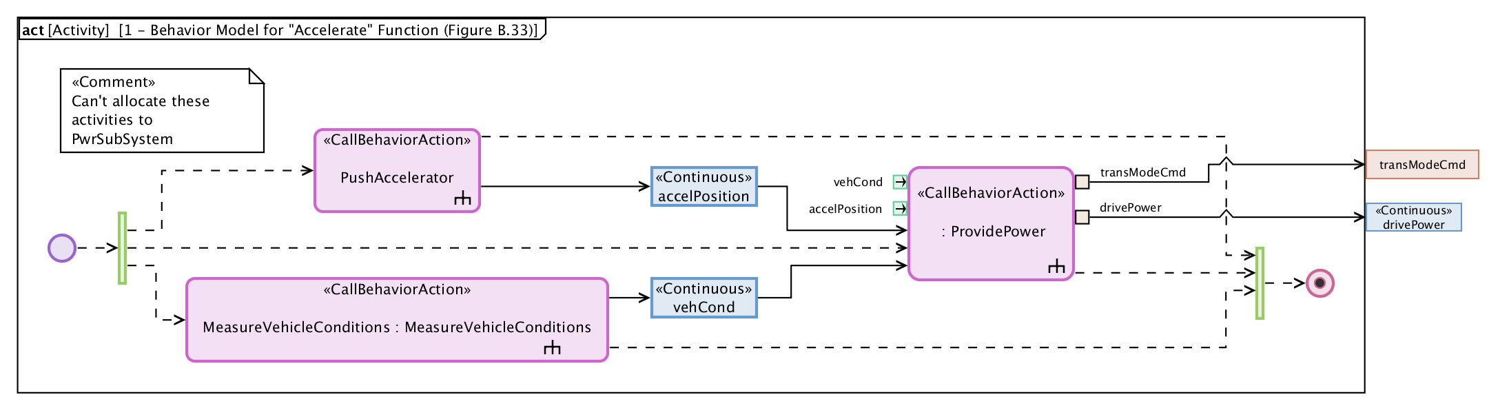
Activity diagram of an electric vehicle accelerate function.
- Activity Diagram: These diagrams provide a dynamic view of the system, showcasing the flow of control and data. Activity Diagrams are key to understanding and modeling complex system operations and workflows.
- Sequence Diagram: Focused on object interactions over time, Sequence Diagrams map out how parts of the system communicate and in what order, making them crucial for understanding system interactions and event-based behavior.
- State Machine Diagram: These diagrams depict the different states of a system or component, including how the system transitions from one state to another. They are essential for modeling life cycles and reactive systems.
- Use Case Diagram: They represent high-level functionalities and interactions between a system and its external entities, such as users or other systems. These diagrams help in visualizing the user perspective and requirements of the system.
Specific SysML Extensions
- Requirement Diagram: Unique to SysML, these diagrams visualize requirements of the system and their interrelationships, tracing the fulfillment of requirements throughout the modeling process.
- Parametric Diagram: They are used to define constraints and performance criteria, integrating engineering analysis with system modeling. Parametric Diagrams are crucial in optimizing design parameters and ensuring the system meets its performance requirements.
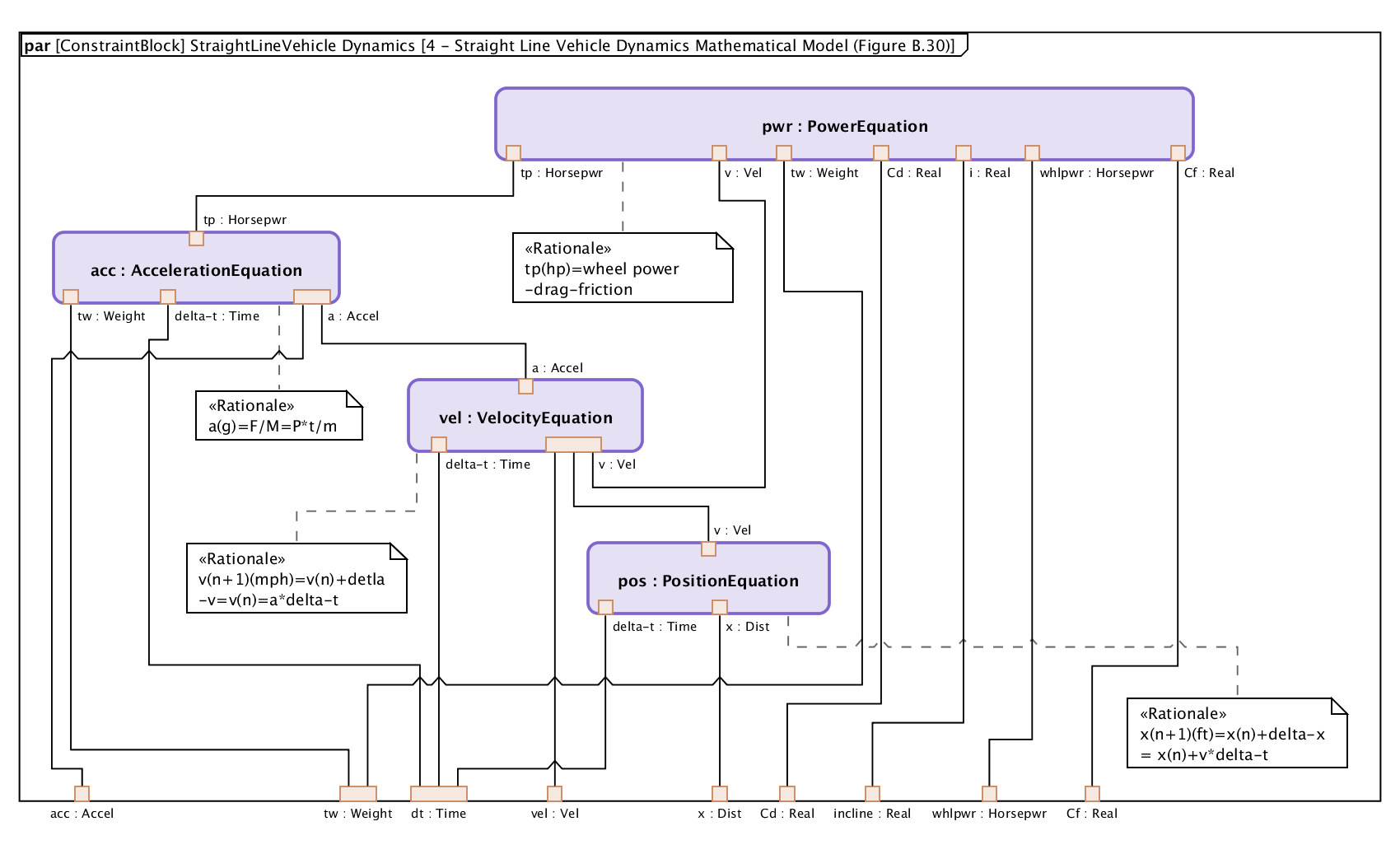
Parametric diagram of the power, acceleration, velocity and position models of an electric vehicle.
Each of these diagrams plays a distinct role in capturing different aspects and dimensions of a system. From the high-level overview of system interactions to the intricate details of its components, SysML Diagrams collectively provide a comprehensive modeling framework. This framework not only aids in the visualization but also in the decision-making process, ensuring that all aspects of the system are coherent and aligned with the project goals.
SysML Diagrams vs. UML: Understanding the Differences
Example UML diagram.
While SysML was originally created as an extension of Unified Modeling Language (UML), it's crucial to understand their distinctions, particularly in the context of system engineering. UML, primarily developed for software engineering, falls short in addressing the multi-dimensional complexities of modern systems engineering. This gap is where SysML Diagrams step in, extending and adapting UML to suit the broader needs of system engineering.
Key Differences
- Scope and Application: UML is predominantly software-centric. In contrast, SysML has a broader application scope, encompassing not only software but also hardware, processes, personnel, and facilities, making it more suitable for comprehensive system engineering projects.
- Diagram Types: While UML boasts 14 diagram types, SysML simplifies this with a focused set of 9 diagrams. SysML omits certain UML diagrams less relevant to systems engineering and introduces new diagrams like Requirement and Parametric diagrams, crucial for systems modeling.
- Abstraction and Simplification: SysML abstracts and simplifies several UML concepts to make them more applicable and easier to use in the broader context of system engineering. This simplification makes SysML more accessible and practical for a wider range of professionals, including those without a deep background in software engineering.
Practical Applications: SysML Diagrams in Action
The versatility of SysML Diagrams is best illustrated through their practical applications in diverse real-world projects. By examining a few case studies, we can appreciate how these diagrams facilitate complex system development and ensure successful project outcomes.
Case Study 1: Aerospace Industry
Example SysML Diagram in Aerospace Industry.
In the aerospace sector, systems engineering is critical due to the complexity and high-risk nature of the projects. SysML Diagrams have been extensively used for designing and visualizing spacecraft systems. For instance, in the development of a satellite, Block Definition and Internal Block Diagrams offer clarity on the satellite's subsystems, such as propulsion, communication, and navigation. Parametric Diagrams play a crucial role in optimizing the design for weight, power consumption, and thermal properties, ensuring the satellite meets its mission requirements.
Case Study 2: Automotive Engineering
Example SysML Diagram in Automotive Engineering.
The automotive industry, particularly with the advent of electric and autonomous vehicles, relies heavily on systems engineering. SysML Diagrams aid in modeling the integration of mechanical, electrical, and software components. For example, in designing a self-driving car, Activity Diagrams and State Machine Diagrams map out the vehicle's operational flows and states, from obstacle detection to decision-making processes. This comprehensive modeling ensures the vehicle's systems work harmoniously and safely.
Case Study 3: Healthcare Systems
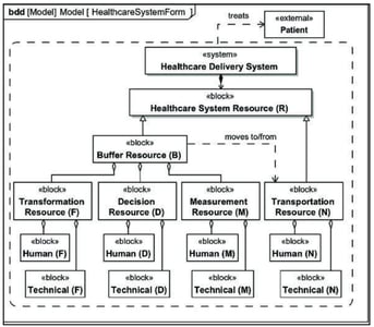
Example SysML Diagram in Healthcare Systems.
In healthcare, systems engineering applies to both the administrative and medical device domains. SysML Diagrams help in structuring patient data flow or in developing complex medical devices. For a medical imaging device, SysML Diagrams provide a clear structure of the device's software and hardware components and their interactions, ensuring compliance with medical standards and patient safety requirements.
The Value in Real-World Engineering
These examples demonstrate the real-world value of SysML Diagrams in simplifying the complexity of modern systems. By offering clear, structured, and comprehensive views of systems, these diagrams enable engineers to anticipate challenges, optimize performance, and ensure robust integration across various system components.
SysML Diagrams not only serve as a tool for visualization but also as a communication medium, bridging gaps between different disciplines involved in a project, ensuring all stakeholders have a clear understanding of the system as a whole.
Best Practices for Implementing SysML Diagrams in Projects
Successfully integrating SysML Diagrams into system engineering projects requires more than just an understanding of their functions. It involves strategic planning and execution. Here are some best practices to maximize the effectiveness of SysML Diagrams in project implementation:
- Clear Definition of Objectives: Before diving into SysML Diagrams, define what you aim to achieve with each diagram. Whether it's to illustrate system architecture, detail component interactions, or map out workflows, having a clear objective guides the modeling process and ensures that the diagrams serve a specific purpose.
- Incremental and Iterative Development: Systems engineering is complex and often involves iterative refinements. Start with high-level diagrams to capture the overall structure and behavior of the system. Gradually add details through subsequent iterations. This approach allows for flexibility and adaptability as the project evolves.
- Cross-Disciplinary Collaboration: SysML Diagrams should facilitate communication across different engineering disciplines. Encourage collaboration by involving team members from various domains in the diagramming process. This collective effort can uncover unique insights and foster a shared understanding of the system.
- Consistency and Standardization: Maintain consistency in notation and terminology across all diagrams. This standardization avoids confusion and misinterpretation, especially in large teams. Adhering to SysML standards ensures that diagrams are universally understood by all stakeholders.
- Integration with Other Tools: SysML Diagrams often need to be integrated with other engineering tools for simulation, analysis, or project management. Ensure compatibility and seamless integration to leverage the full potential of these tools alongside SysML modeling.
- Training and Skill Development: Given the specialized nature of SysML, invest in training for team members. A team well-versed in SysML can more effectively utilize these diagrams for system modeling and analysis.
- Regular Reviews and Updates: System requirements and designs can evolve during a project. Regularly review and update the SysML Diagrams to reflect these changes. Keeping diagrams current ensures they remain useful throughout the project lifecycle.
By following these best practices, teams can effectively leverage SysML Diagrams to conceptualize, design, and communicate complex systems, thereby enhancing the overall efficiency and effectiveness of system engineering projects.
Overcoming Challenges with SysML Diagrams
While SysML Diagrams are powerful tools in systems engineering, their implementation is not without challenges. Addressing these challenges head-on is crucial for leveraging the full potential of SysML in project development. Here are some common obstacles and strategies for overcoming them:
- Complexity of SysML: SysML's comprehensive nature can be overwhelming, especially for newcomers. To mitigate this, it's essential to provide focused training and resources. Start with the basics of the most commonly used diagrams before delving into more complex aspects.
- Integration with Existing Processes: Introducing SysML into an established workflow can be challenging. Gradual integration, rather than a complete overhaul, can ease this transition. Start by incorporating SysML Diagrams into smaller components of the project before scaling up to larger systems.
- Ensuring Stakeholder Buy-In: Not all stakeholders may be familiar with SysML, which can lead to resistance in adopting these diagrams. Demonstrating the tangible benefits of SysML through case studies or pilot projects can help in gaining their support. Clear and simplified presentations of SysML Diagrams can also aid in this process.
- Balancing Detail and Clarity: One of the challenges in using SysML is determining the appropriate level of detail. Overly detailed diagrams can become confusing, while too little detail might render them ineffective. Striking a balance is key—provide enough detail to be useful while maintaining clarity and readability.
- Tool Selection and Proficiency: The effectiveness of SysML Diagrams heavily depends on the tools used for their creation and analysis. Selecting the right modeling tools that are compatible with project needs and ensuring the team is proficient in using them is crucial.
- Keeping Diagrams Updated: Systems evolve, and so should their corresponding SysML Diagrams. Regular updates to the diagrams to reflect changes in the system ensure they remain relevant and useful throughout the project lifecycle.
By addressing these challenges with thoughtful strategies, teams can harness the full power of SysML Diagrams, turning potential obstacles into opportunities for enhanced project clarity and success.
Future of SysML Diagrams in System Engineering
As we look towards the future, the role of SysML Diagrams in system engineering is poised to evolve and expand. Emerging trends and technological advancements are shaping how these diagrams will be used to model increasingly complex systems. Here are some key developments and predictions:
- Integration with Advanced Technologies: With the rise of AI, machine learning, and the Internet of Things (IoT), SysML Diagrams are expected to integrate more deeply with these technologies. This integration could lead to more intelligent and automated system modeling, offering enhanced predictive capabilities and optimization insights.
- Enhanced Interoperability: As projects become more interdisciplinary, the need for SysML Diagrams to interoperate with various other engineering and project management tools will grow. Future developments in SysML are likely to focus on enhancing compatibility and ease of integration, facilitating smoother collaboration across different tools and platforms.
- Expansion into New Domains: While SysML has its roots in aerospace and defense, its application is expanding into new sectors such as healthcare, environmental engineering, and smart city development. This expansion will drive the evolution of SysML Diagrams, tailoring them to meet the unique needs of these diverse domains.
- Increased Emphasis on Usability: Recognizing that the complexity of SysML can be a barrier, future versions are expected to focus on user-friendliness and accessibility. This might include more intuitive diagramming tools, better documentation, and enhanced training resources.
- Continuous Standardization Efforts: As SysML evolves, continuous efforts in standardization will be crucial to maintain consistency and interoperability in system engineering practices globally. These efforts will ensure that SysML remains a reliable and universally accepted modeling language.
- SysML in Education: With the growing importance of systems engineering, incorporating SysML into engineering education will become more prevalent. This early exposure will prepare the next generation of engineers to effectively use these diagrams in their professional careers.
Conclusion: The Indispensable Value of SysML Diagrams
In summarizing the role of SysML Diagrams in effective system engineering, it's evident that these tools are not merely beneficial but indispensable in the modern engineering landscape. From conceptualization to deployment, SysML Diagrams offer a structured, comprehensive, and flexible approach to modeling complex systems. They bridge gaps between various engineering disciplines, foster clear communication among stakeholders, and provide a platform for collaborative problem-solving.
The intricacies of SysML have highlighted its versatility across different industries, from aerospace to healthcare, and its capability to evolve with emerging technologies and future demands. SysML Diagrams have demonstrated their crucial role in not only simplifying complexity but also in enhancing the efficiency and effectiveness of system engineering projects.
As we look forward, the continuous evolution of SysML in response to new challenges and technologies will further cement its role in systems engineering. By embracing these changes and adhering to best practices, engineers and project managers can leverage SysML Diagrams to achieve greater innovation, precision, and success in their endeavors.
SysML Diagrams support the ongoing quest for excellence in systems engineering, offering a view of the intricate workings of complex systems and a tool for shaping the future of technological advancements.
About the Author
Santiago Leon, Senior Product Development Engineer at Tom Sawyer Software, is passionate about software tool development and design. He is active in the Object Management Group (OMG) and has taken part in the development of the SysML 2.0 Specification, focusing on the graphical visualization of models.
FAQ
How do SysML Diagrams integrate with Agile methodologies in systems engineering?
SysML Diagrams can complement Agile methodologies by enabling continuous modeling throughout the iterative development process. Agile teams can start with high-level SysML Diagrams, such as Block Definition Diagrams, and progressively add detail as the system evolves, aligning with Agile’s focus on adaptability and incremental development. By updating SysML models regularly, teams maintain an accurate, evolving system architecture.
Are SysML Diagrams suitable for large-scale systems, such as those in the aerospace or defense industries?
Absolutely. SysML Diagrams are particularly well-suited for large-scale systems due to their ability to model complex architectures involving multiple components, subsystems, and interactions. In the aerospace and defense industries, SysML is often used to manage the extensive requirements, system behaviors, and component relationships that such systems demand.
Can SysML Diagrams be used in conjunction with model-based systems engineering (MBSE) approaches?
Yes, SysML is a core language for Model-Based Systems Engineering (MBSE). MBSE focuses on creating a comprehensive system model rather than relying on traditional document-based methods. SysML Diagrams are used to represent the system structure, behavior, and requirements within the MBSE framework, improving collaboration, system understanding, and consistency across teams.
What role do SysML Diagrams play in regulatory compliance?
In industries that require strict regulatory compliance, such as aerospace, healthcare, or defense, SysML Diagrams can help maintain traceability between system requirements and design elements. Requirement Diagrams ensure that regulatory requirements are clearly defined and linked to the corresponding system components, making it easier to demonstrate compliance during audits or certification processes.
How can SysML Diagrams help manage system complexity in large projects?
SysML Diagrams are particularly valuable for managing complexity in large projects by breaking down the system into more manageable components. Diagrams like Block Definition Diagrams and Internal Block Diagrams offer a hierarchical view of the system architecture, making it easier to understand the relationships between subsystems and components. This modular approach improves project management and system integration.
Submit a Comment